
Anti-jamming Design and Temperature Control System of Control System of Inverter Submerged Arc Welding Machine
2021-04-19
Submerged arc welding is widely used in industrial production. It has the advantages of high production efficiency, high weld quality, relatively good working conditions, etc. However, the traditional submerged arc welding power supply not only consumes a lot of power, but also has many consumables and the wire feeding circuit is complicated. This is incongruous with the current level of microelectronics, computer control technology and power electronics technology.
The inverter power supply features small size, light weight, low power consumption, and high efficiency. With the development of power electronics technology, the emergence of new high-voltage, high-capacity, integrated, full-control, high-frequency, multi-functional, and intelligent power module devices has brought new opportunities for the development of inverter power supplies. The use of single-chip controlled arc welding inverter power supply, using its good dynamic characteristics and welding process performance will be more conducive to control the entire arc welding process and improve welding quality. The control circuit of the welding machine adopts INTEL 16-bit microcomputer (8OC196KC) to control. The control circuit must complete functions such as data acquisition, program control and power supply external characteristic control. Therefore, the reliable work of the SCM is undoubtedly one of the key factors for the reliable work of the whole welding machine. . In order to minimize the adverse effects of various interferences, in addition to carefully selecting components and precision components that have high integration, strong anti-interference ability, and low power consumption, they must also have hardware and software. Some specific anti-jamming measures taken by the system can ensure stable and reliable operation.
1 Source of interference
The source of the interference is the component, device, or signal that caused the interference. The interference sources of the SCM system mainly include the thermal noise of electronic components, the electromagnetic interference generated by electrical and electronic devices, the impact of high-power devices on the power grid, and the electromagnetic waves emitted by high-power radio, television, and communications equipment, and the system itself. The transition process, PCB layout design is not reasonable and so on.
Interference can invade the microcontroller system along various lines. Interference in the industrial environment generally enters the system in the form of pulses. There are three main channels: First, the spatial interference (magnetic field interference), the electromagnetic signal enters the system through space radiation; the second is the process channel interference, interference through the forward channel connected to the system, The backward channel and the mutual channel with other systems enter; the third is the interference of the power supply system, and the electromagnetic signal enters the system through the power supply line.
2 hardware anti-jamming technology
The hardware anti-jamming design is the preferred anti-jamming design scheme when designing the system. It can effectively suppress the interference source and block the interference propagation path. Arranging and selecting the relevant parameters reasonably can suppress most of the interference of the system.
2.1 Host Unit Configuration Anti-jamming
The parts of the microcontroller system that are most susceptible to interference include the reset circuit and the clock circuit. The usual reset circuit uses an RC reset circuit, see Figure 1a. This method provides a reset time of less than 5Oms. If you increase the reset capacitor, it will make The reset signal generated by the watchdog timer WDT (WATCHDOG TIMER) hardly works. The system uses the MAX705 supervisory chip, which can output a low-level reset pulse with a width of up to 200ms, enough to guarantee a reliable reset of the 80C196KC. In addition, it has the functions of voltage monitoring and watchdog. To avoid stray charges RESET is an error condition. A pull-down resistor is connected to the RESET pin to absorb stray charges and keep the reset signal low. In addition, in order to avoid frequent reset caused by glitches on the power supply voltage due to noise, the microcontroller Connect a 0.1 μF ceramic capacitor between the power pins of the digital IC and the monitor and the ground. Use the MAX705's reset circuit as shown in Figure 1b.
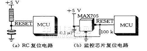
Figure 1 single chip reset circuit
The clock circuit generates the timing pulse of the CPU, which is a key part of the normal operation of the CPU. Many of the interference is the destruction of the normal operation of the clock, resulting in the CPU out of control. Figure 2 shows that the clock will change the clock after superimposed noise interference. Divide the signal, cause the CPU working sequence to be disordered. This system adopts the 12MHz crystal oscillator, the most influential high-frequency noise that the one-chip computer produces is about 3 times of its clock frequency.
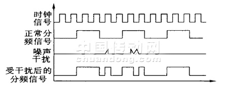
Figure 2 Noise Interference with Clock Signals
In order to avoid interference caused by the clock circuit, the following anti-jamming measures are taken in the PCB layout of the system:
(1) The clock pulse circuit is configured close to the microcontroller 80C196KC, using thick and short leads.
(2) The oscillation circuit is surrounded by a ground wire and the crystal case is grounded.
(3) The capacitor of the crystal oscillator circuit uses a capacitor with stable performance and accurate capacitance value and is far away from the heating element.
(4) The connection of the high-current signal line and power transformer on the printed board is far away from the crystal signal.
2.2 Power Supply Interference
In the control system of the single-chip microcomputer, the interference with the most serious harm comes from the noise of the power supply. The internal resistance of the power supply is the main cause of the interference noise of the power supply. Without this internal resistance, any interference noise will be short-circuited by the power supply and will not cause any interference voltage in the line. But in fact, the internal resistance of the power supply cannot exist. Because power noise mainly comes from the use of some high-power devices and the unreasonable configuration of the power supply itself.
The power supply interference of the data acquisition of the one-chip computer is mainly caused by the appearance of over voltage, under voltage or spike voltage. The dangers of overvoltage and undervoltage are obvious. It will make the DC supply voltage of the system deviate from the allowable range, and it is in an abnormal state. For the spike voltage, because it has a short duration, it will not damage the system, but it will greatly damage the normal operation of the microcontroller. It will disturb the logic function and even damage the source program. The solution to the above problem is to use an AC with noise suppression capability. Power regulators and regulators.
2.3 Electromagnetic interference
The high-frequency transformer in the welding machine operates at a frequency of 20 kHz, and its leakage flux is a large source of interference. In addition, the high-frequency current also generates power lines and magnetic lines around the high-frequency changes, thus forming a kind of space. Propagation of electromagnetic waves. Two measures are adopted in this system: shielding and twisted pair transmission. First, the entire welding machine is isolated into several different areas with a metal shield. The SCM control system is placed in a separate area, and the transformer and power switch tube Other parts that have strong electric field, magnetic field, and electromagnetic field interference are placed in another area. The surrounding shields are used to block the coupling of the space field. In addition, iron plates are used on the sides of the transformer to provide a loop for magnetic flux leakage. Non-conductive may also be used. Magnetic materials such as aluminum partitions leak magnetic. Twisted pair has a strong ability to suppress electromagnetic induction interference, the system uses twisted pair and optocoupler to complete the transmission between the main control board and wire feed circuit board.
2.4 Isolation and Grounding
Welders include both weak control and strong control. It is necessary to maintain the connection between the control signals and the connection between the two sides. That is, the implementation of weak current and strong electrical isolation is an important measure to ensure the stability of the system and the safety of the equipment operators. The system uses optocoupler and relay two isolation methods. All analog and digital input and output channels in the system are generally isolated by optocoupler: the power interface between weak current and strong current is isolated by a relay; in some parts, optocoupler and relay isolation are also adopted. This avoids direct contact between them and reduces their degree of harm. In addition to isolation, grounding techniques are also an important means of suppressing noise. A good grounding can largely suppress the noise coupling inside the system, prevent the intrusion of external interference, improve the system's anti-jamming capability, and adopt the following practices:
(1) On the printed circuit board, separate the digital ground from the analog ground and connect it to the ground at the power supply end.
(2) Analog signal lines to avoid ergonomic traces. In addition, the ground line should be as thick and wide as possible to form a loop. The printed circuit board power leads are grounded at one point.
(3) Float the digital and analog grounds of the control system. The shield of the welding machine and the control power supply is grounded to prevent static electricity and electromagnetic induction. In addition, other anti-jamming measures are included in the hardware anti-jamming system that are not counted, such as: electromagnetic anti-jamming, decoupling capacitor anti-jamming, inductive load anti-interference, and mechanical switch contact anti-jamming.
3 software anti-jamming measures
In order to improve the reliability of the control system, hardware anti-jamming measures alone are far from enough, and appropriate software anti-jamming measures are also needed. The software anti-jamming technology is to remove false positives or interfere with the system when the input signal is disturbed. An auxiliary method to restore the system to normal operation.
3.1 Watchdog Timer (WDT)
WDT can be implemented by hardware, but also by software. The system uses the reset chip MAX705 itself with a hardware watchdog function, while the system uses the 80C96KC's own watchdog function, the essence of which is a l6-bit counter. When it starts up, its count increases by 1 during each state cycle. If it is cleared by an instruction in the 64K state cycle (this system uses a 12 MHz crystal oscillator, about 11 ms), the counter overflows and RESET is asserted. Pull down at least 1 state cycle to reset the system and reinitialize.
3.2 Data acquisition anti-jamming measures
For real-time data acquisition systems, digital filtering methods are used to resist interference. The methods of digital filtering include: program determination filtering, median filtering, arithmetic average filtering, weighted average filtering, first-order lag filtering, and composite filtering.
Digital filtering has the following advantages:
(1) The digital filter is implemented by a program, no need to add hardware equipment, high reliability and good stability.
(2) The digital filter can filter the signal with very low frequency, while the analog filter is influenced by the capacity of the capacitor, and the frequency cannot be too low.
(3) The digital filter can use different filtering methods or filter parameters according to the different signals, which is flexible, convenient, and powerful.
3.3 Redundancy instructions
The one-chip computer most susceptible to interference is the value of the internal program counter PC. After being strongly disturbed, the PC value is changed. The changed value is random and uncertain. It will often cause the microcontroller to program.
Jumping from the correct position to an indeterminate area continues execution, or the operand is executed as an opcode, causing program confusion. Therefore, in the preparation of the program, as few as possible multi-byte instructions, and consciously insert some no-operation instructions NOP in the key place, which is redundant instructions. The insertion of redundant instructions can reduce the number of program bombs, when bombs When the flying program encounters these empty instructions, the content of the PC is adjusted so that the program can quickly be put into the correct track. In addition, the 0FFH value is filled in all the unused memory cells, that is, the destination code value of the reset instruction RST. When the program is bombed into these areas, it will be reset to avoid the system's paralysis.
3.4 Software Traps
When the runaway program enters the non-program area, the redundant instruction will not work. At this time, the runaway program can be intercepted by the software trap, and it can be led to the designated location and then the error processing can be performed. The software trap is used to force the captured runaway program to the entry address of the program that specifically handles the error. Assuming that the entry address of the program that handles this error is ERROR, the following three instructions form a software trap: NOP NOP LJMP. ERROR usually fills in such a software trap in the EPROM non-program area. Because the software traps are all arranged in places where normal programs cannot be executed, the execution efficiency of the program will not be affected.
4 Conclusion
(1) The system analyzes various interferences that may affect the normal operation of the welding machine control system and the original Oka of the cows produced, and takes corresponding anti-disturbance measures from both the hardware and software aspects.
(2) The basic anti-interference of the SCM practical application system is that hardware and software anti-jamming only play a supplementary role. Therefore, in the design of the system, only the two can take care of each other and complement each other to achieve a good anti-jamming effect.
(3) Tests by the welder showed that the above-mentioned hardware and software measures were effective and effective, and received good results, which solved the interference problem of the inverter submerged arc welding machine control system.
Temperature Control Management:
Product Name: Japan Yamatake YAMATAKE products for automatic welding machine program Product Model: Japan YAMATAKE
a brief introdction:
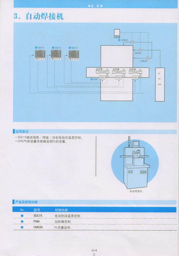
SDC15 temperature controller provides preheating/welding/cooling temperature control for each section.
CMS gas flow sensor monitors the flow of N2.
1. SDC15 heating section temperature control
2. PGM heater control
3.CMS20 N2 traffic monitoring
Our Welding Line force control system, Welding Line constant force actuator, Welding Line active contact flange have many advantages over other grinders. It can realize flexible grinding, quick repsond to surface changing, and instant adjusting. Traditional mechanic hand lacks flexibility, and it is not easy to adjust, hard to realize mass production.
Welding Line Constant Force Actuator, Welding Line active contact flange, Welding Line force control system
Genour Power Machinery Ltd. http://www.szactivecontactflange.com